
'VPW'에 해당되는 글 3건
- 2008.11.14 OBD Chip Schematic 1
- 2008.10.29 ElmScan VPW Scan Tool
- 2008.10.06 Reference Schematics - Car OBD II J1850 PWM, J1850 VPW, ISO-9141 cables schematic pinout
OBD-2 universal cable scheme forPWM,VPW, andISO 9141-2 vehicles pinout
This device is a CMOS microcontroller which is designed to interface a personal computer or laptop with a vehicle"s On Board Diagnostic (OBD II) interface. It is intended to function with all three of the protocols used by vehicle manufacturers to implement the OBD II system as defined by SAE and ISO specifications. The OBD II system became mandatory for 1996 and up vehicles, but some vehicles were already fully or partially compatible with OBD II requirements prior to 1996. The chip is not suitable for the earlier vehicles such as OBD I. The device is intended to function as a simple scan tool and is capable of sending and receiving any OBD II message defined in SAE J1979 for any of the three types of OBDII bus implementations (PWM, VPW, ISO 9141-2). It can also be used as an inexpensive interface for custom instrumentation monitoring various vehicle parameters such as speed, RPM, coolant or intake air temperature, engine load, intake air flow rate, etc.
Components:
C5, C6  .01 UF, 25V
C4      .1 UF, 25V
C3      .47 UF, 50V
C2,C1    20 pf, 50V
R11, R12, R23, R9, R1, R3, R4, R25, R8  10 KOhm, 1/4 Watt
R24 18 KOhm, 1/4 W
R19, R18, R7, R20, R22, R5, R6, R13 1 KOhm, 1/4 W
R21 5.6 KOhm, 1/4 W
R16, R17 510 Ohm, 1/4 W
R10 62 KOhm, 1/4 W
R15 9.1 KOhm, 1/4 W
R14 270 Ohm, 1/2 W
R2   - Not used
D2  1N4739 Zener, 9.1V, 1W
D1, D3  1N4148 Diode
Q3, Q4, Q5 PN2222 Transistor, NPN
Q2 PN3904 Transistor, NPN
Q1 PN3906 Transistor, PNP
IC2 7805 Regulator, 5V
IC3 LM339N Quad Comparator
IC1 16F84-20 Microprocessor (firmware 1.07)
XTL 1 20 MHz Crystal, 20 Mhz
If you don"t use PWM, you can omit R4, R6, R7, R8, R9, R10, Q1, Q2, D1.
If you don"t use ISO, you can omit R15, R16, R17, R18, R19, R21, Q4, Q5
If you don"t use VPW, you can omit R13, R14, R23, R24, D2, D3, Q3
Don"t connect external power sources - all power direved from pin 16 of OBDII
Serial port works at 19200 baud
Scheme is unuseful without .hex for IC1 firmware 1.07...
Can be replaced using scheme with ELM327 chip (http://www.elmelectronics.com/DSheets/ELM327DS.pdf). ELM327 even prvides more protocols, including CAN.
VPW 형식을 지원하는 Scanner $34 불로 저렴한 편이다.

P/N: 420301
The ElmScan VPW Scan Tool can be used with our free software to turn your computer into a sophisticated auto diagnostic system. This interface supports the J1850 VPW protocol used mostly in General Motors vehicles..
Description
ElmScan VPW scan tool supports the J1850 VPW protocol used mostly in General Motors vehicles. Be sure to determine the communication protocol used in your vehicle before purchasing this scan tool.
| Processor: | ELM322, crystal-controlled for accuracy |
| OBD-II Protocols: |  J1850 VPW (Variable Pulse Width) J1850 VPW (Variable Pulse Width) |
| Output protocol: | RS232 |
| Indicator LEDs: | OBD Tx/Rx, RS232 Tx/Rx, Power |
| Operating voltage: | 12V, internal protection from short circuits/overvoltages |
| Dimensions: | 3"x4" (76x102 mm) |
Diagram

Reference Schematics - Car OBD II J1850 PWM, J1850 VPW, ISO-9141 cables schematic pinout
| Car/Engine 2008. 10. 6. 21:29Alarms and security related schematics
- Proximity alarm
- Electronic lock
- Electronic door codelock (PIC16F84)
- Ultrasonic remote control & alarm system
- Wire loop alarm
- Door knob alarm (PDF)
- Water seepage alarm (PDF)
- Micro-power over temperature alarm (PDF)
- Personal silent alarm system
- Active IR motion detector
- Frost alarm
- Ultrasonic radar alarm
- Refrigerator door alarm
- Emergency Light & Alarm
- Electronic combination lock
- Proximity detector for humans / living creatures using eddy current detection
- A Basic RF Transmitter for PIR Sensors
- PIR motion detector
- Simple alarm system
- Home security project
- 5 Zone alarm circuit
- Miniature loop alarm
- Novel Buzzer
- Gate alarm circuit
- Modular Burglar Alarm
- Motorcycle alarm
- Enhanced 5 Digit Alarm Keypad
- Enhanced 4 Digit Alarm Keypad
- RF Alarm
- Single Zone Alarm
- Water Activated Alarm
- Water level alarm
- Perimeter monitor
- Digital combination lock
- Alarm control keypad
- Almost Ultrasonic Motion Sensor
- 2-input alarm
- Touch activated alarm system
- Combination Lock (PIC16F84)
- Low power RFID transponder (PDF)
Audio power amplifier schematics
- Two transistor audio amplifier
- Personal stereo audio amp
- Headphone amplifier
- 1.5W Audio amplifier
- Low-level audio amp
- 10W amplifier
- 80W amplifier
- LM383 12V Amplifier
- 4W amplifier
- 8 watt audio amp
- 20W Amplifier
- 50W Amplifier
- 100W RMS Amplifier
- 2-Channel Power Amplifier
- 25W MOSFET audio amplifier
- 50W audio amplifier using ICL8063
- Amplified ear for surveillance
- 20dB VHF Amplifier
- 30 watt FM linear amplifier
- Linear FM 50 watt amplifier with BLY90
- 60W RF linear amplifier using IRF840
- Push-Pull Class A Amp using type 5687 dual triodes
- Push-Pull Class A 2A3 Stereo Amp
- Single Ended Class A2 SV811-10 Stereo Amp
- Compact 50W Integrated Amplifier with Meier Headphone Section
- Audio amplifier output relay delay
- Spatial Distortion Reduction Headphone Amp
- HeadBanger Headphone Amp
- 2W Amplifier
- TDA2030 8 Watt amplifier
- Headphone monitor amp
- 50W audio power amplifier
- Bi-Directional 2.4 GHz One Watt Amplifier
- Bi-Directional 900Mhz One Watt Amplifier
- 20 Watt GaAaFET Power on 2.3 GHz
- 1 Watt 2.3 GHz RF Amplifier Using a MRF2001
- 2.3 GHz Power Amplifiers
- 2304 and 3456 MHz Power Amplifiers
- High quality exponential VCA
- 16 Watt amplifier
- 8 Watt amplifier
- 20 Watt Class-A Power Amplifier
- El-Cheapo - A Really Simple Power Amplifier
- Single Chip 50 Watt / 8 Ohm Power Amplifier
- Hi-Fi Headphone Amplifier
- 100W Guitar Amplifier
- Death of Zen (DoZ) - A New Class-A Power Amp
- Soft-Start Circuit For Power Amps
- Thermo-Fan To Keep Your Amp Cool
- Audio Amp Output Power Limiter
- 55W (Originally 75W) Power Amplifier
- 300W Subwoofer Power Amplifier
- 20 Watt / Channel Stereo Power Amplifier
- Mini bench amplifier (LM386)
- Small bench amplifier ideal for testing audio stages in circuits
- 12 Watt Valve Guitar Amp
- Five Tube Stereo Amplifier
Audio preamp circuits
- Microphone amplifier
- RIAA phono amplifier
- Low impedance microphone amplifier
- High quality audio preamplifier (OPA2134)
- Masthead preamp
- Preamplifier for microphone or guitar use
- Simple microphone preamplifier
- Tube microphone preamp
- Simple Stereo Electret Microphone Preamplifier
- Simple Stereo Electret Microphone Preamplifier
- Phono Preamp
- Simple microphone preamplifier
- ECM Mic preamp
- Hi Fi preamp
- Balanced microphone preamp
- Electret mic amplifier
- Audio preamplifier
- Vacuum Tube Microphone Preamp
- FET Preamp Cable
- Altec 1564A Preamp Power Supply
- Neumann U67 microphone preamp power supply
- Audio preamp
- Telefunken/Siemens/Maihak/TAB V72 microphone preamp schematic
- Altec 428B Microphone Preamplifier schematic
- API 321 mic preamp schematic
- RCA BA-1A two-stage preamp schematic
- RCA BA-21A preamplifier schematic
- RCA BA-31A preamplifier schematic
Automative, car and motorcycle schematics
- Electronic auto stethoscope
- Turn signal alarm
- Motorcycle turn-signal system
- Cigarette lighter 9V adaptor
- Adaptive Windscreen Wiper Control
- Car OBDII diagnostic interface cable schematic pinout
- Car OBD II J1850 PWM, J1850 VPW, ISO-9141 cables schematic pinout
- Grand Cherokee Off-Highway Lights
- Engine control unit schematics
- Portable CD Player Adapter For Car
- Car battery charger
- Wireless Auto Tachometer
- Headlight reminder
- Breath Alcohol Tester controlling a car ignition system
- Simple car battery charger
- Flashing / pulsing third brake like for cars
- Headlight flasher
- Speed alert - wireless portable unit
- Parking aid senses distance to rear of vehicle
- Automatic headlight brightness switch
- Car battery charger circuit
- Electronic car ignition circuit
- Car battery voltage tester using LM3914
- Synchronized multi-spark module (SMSM) for Electronic Ignition Devices (EID)
- Economy radar detector
- Headlight timer
- Parking sonar
- Fuel injector pulse width monitor
- BMW R Series Motorcycle Regulator Schematic
- 80188XL Engine Tachometer
- Simple Car Preamplifier and Artificial Earth
- Breakdown safety beacon
- FCD (Fuel Cut Defencer)
- Interface between GM's 5 Volt 8192 baud ALDL data stream and a PC serial port
- 5301 wideband fuel mixture display
- Wide Band Fuel Mixture Display
- 3rd brake light
- 12V to 9V car coverter
- Car Nicad charger
- Combination lock for car liftgate
Data acquisition (DAQ) and data logging schematics
- Air flow detector
- Air flow detector
- Strain gauge sensor
- Digital Water Wave/Tide/Level Meter (PIC16F876)
- 8 Photo-Detector Circuit Board
- Self made data-logger V2.5 (second edition)
- Magnetometer
- Analog input section based on AD9220
- uModem 4+4/8 channel A/D board
- ADXL202 accelerometer to CV output
- Universal flight controllers / datalogger
- Rain detector
- Home Brew Compass Sensor
- Using 555 Timer as an A/D converter
- ADC0804LCN 8-bit A/D converter
- Web-based thermometer project
- Honey Bee counter (PDF)
- Capacitance type liquid level measurement (PDF)
- Thermostat node schematic
- Digital PC Oscilloscope
- Ultrasonic Range & Imager
- Precision Digital Altimeter
- Remote digital thermometer sends data over AC power line
- 4-channel data telemetry system
- Voltage follower with 1G ohm input resistance
- Digital compass schematic
- Temperature datalogger
- Serial Port A/D-converter
- Centronics port D/A converters and low-pass filter
- LCD Thermometer
- Wireless Liquid Level Sensing for Restaurant Applications
- Accelerometer Schematic
- Pressure Sensor-Based Altimeter Circuit
- Ultrasonic range finder circuit
- 1-wire barometer
- Water-level sensor
- Addressable ADC
- Electronic altimeter using PIC16F877
- Wireless weater station
Filter schematics
- Galaxy Noise Filter
- Low-pass active filter
- Filter Circuit for the Earthworm Seismic Data Acquisition System
- 45 to 90Hz hum filter
- Active 2nd Order Filters
- RC Notch Filter (Twin T)
- 'A' Weighting Filter For Audio Measurements
- Multiple Feedback Bandpass Filter
- CW filters
- Self-tune filter
- SSB AF filter
- CW Filters
- Self-tuning CW filter
- SSB AF filter
- Helical Resonator Notch Filter
- 3KHz low-pass filter plus audio amp (PDF)
- Active bandpass filters
- Bandpass filters
- Butterworth filters
- Narrow band audio bandpass filter
- Chebyshev Bandpass Filter
- Bandpass filters
- Chebyshev / Butterworth filters
- Biquad Active Bandpass Filter Schematic
- "A" Weighting Filter For Audio Measurements
- Multiple Feedback Bandpass Filter
- Digital signal processor (DSP) for radio communications
- 29.85 MHZ bandpass filter schematic
- 29.85 MHZ notch filter schematic
- Variable notch filter with both high and low pass filters
- LC filter design
Games and fun stuff (electronic schematics)
- Visor cradle serial interface
- Electronic coin tosser
- Electronic craps game
- First response monitor
- VCR ping pong game
- Video ping pong game
- MBC5/CPLD for the GameBoy
- GameBoy Camera Parallel Port Interface
- PSX controler to PC MIDI converter
- Dreamcast PC serial adapter
- GameBoy Cart Programmer
- 32 Kb x 8 emulator for the GameBoy
- Project: NES to Atari 2600 controller interface
- Battery Meter for Pinball Machines
- SRX1 (Stephane's Robotic eXperiment 1)
- Pine Racecar Victory Judge
- Interfacing Sony control stick to Empeg
- Electronic Nicad glow plug driver
- Multi-User Jeopardy Game (Fastest Finger First)
- Quiz show indicator
- Dreamcast interface
- Flashing heart
- Phoenix programmer
- Funcard programmer
- Bingo!!! (on your tv)
- Slot car TV cronograph
- Furby reverse-engineered circuit
- Sanyo 20EZ monitor Arcade Game (300k ZIP)
- Burger Time Arcade Game (500k ZIP)
- Dig Dug Arcade Game (800k ZIP)
- Frogger Arcade Game (500k ZIP)
- Galaga Arcade Game (542k ZIP)
- Gyrus Arcade Game (800k ZIP)
- Junior Pacman Arcade Game (400k)
- Ladybug Arcade Game (335k ZIP)
- Mappy Arcade Game (470k ZIP)
- Moon Cresta Arcade Game (300k ZIP)
- Mr.Do Arcade Game (554k ZIP)
- PacLand Arcade Game (316k ZIP)
- Pengo Arcade Game (313k ZIP)
- Q*Bert Arcade Game (600k ZIP)
- Qix Arcade Game (476k ZIP)
- Scramble Arcade Game (600k ZIP)
- Time Pilot'84 Arcade Game (870k ZIP)
- Xevious Arcade Game (450k ZIP)
- Magic Wand Conjuring Trick
- Quiz game circuit
- E.S.P. Conjuring Trick
- Space invaders game using PIC microcontroller
- DIT shutterglasses controller
- Tic-tac-toe game using PIC16F628
- Hangman game
- LED dice with slow down tumbling action
- LED Zeppelin game of skill and patience
- Lotto number selector helps you win a fortune
- Simon Says memory game using a PIC16F84A or PIC16F628 microcontroller
- Spin the device educational project based on PIC12F629 microcontroller
- Tic Tac Toe game based on Microchip PIC16F628 microcontroller
- Game Show Timers
- Archery timer
- Coin tosser
- PIC micro Tetris game
- Magic lamp, IR remote control jammer and other fun circuits (PDF)
- Lego Mindstorms Double Rotation Sensor
Infrared based schematics
- IR detector
- Infrared body heat detector
- Stereo IR audio receiver
- General purpose IR receiver
- Wireless IR headphone transmitter
- Wireless IR headphone receiver
- Infrared Receiver Module Schematics
- Infrared transmitter for locomotives
- Infrared gate for door
- Infrared circuits for remote control
- Serial port controller infrared transmitter (PIC16F628)
- Digibox interface
- IR remote control
- 40KHz light receiver (PDF)
- 40KHz TV-VCR repeater (PDF)
- Micro based PIR to IR remote converter
- IR-related ASCII Schematics V1.00
- Infrared remote transponder
- Build an Infrared night scope
- Decoding IR Remote Controls
- IR detector
- PC IR Remote Control Hardware
- PC IR Remote Control
- An Ambient-Light-Ignoring Infrared Active Motion Detector
- Simple on-off IR photoswitch without use of comparators
- Infrared gate (door entry alarm)
- Infrared switch using any infrared remote control
- Improved infrared receiver for PC with status LED
- Infrared link for 10-BASE-T / 100-BASE-T PC network card
- iRDA transceiver to extend IR port range up to 15 meters
- Infrared level detector for liquid level detection and proximity detection
- IR remote control tester
- Infrared Transmitter and Receiver schematic diagrams
- Pyroelectric Infrared Sensor
- Minimal Infrared transmitter for PC
- Simple IR transmitter circuit
- Simple infra-red detector
- Infra Red Switch
- IR remote control extender
- IR Remote Control Extender Circuit (Mark 2)
- IR Remote Control Extender Circuit (Mark 3)
- IR Link
- IR remote control tester
- 40khz IR Tester
- 555 timer 40khz IR Oscillator
- IR detector / emitter
- Fire-Stick infrared remote control
- Simple infrared remote control
- Infrared / Ultrasonic beacon
- Implementing Infrared Object Detection
- Computerized Infrared Remote
Laser related power supplies and data transmission
- Light beam receiver for laser pistols
- 12V supply for He-Ne laser
- Laser diode transmitter
- Low Cost Scanning Laser Rangefinder (PDF)
- Sniper tag laser beam detector
- Laser high-voltage power supply
- Laser power supply
- Laser transmitter/receiver
- Time of flight imagine (PDF)
- Laser harp
- Laser light output intensity meter
- 20MHz VCSEL 3mW laser test circuit (PDF)
- 10MHz to 20MHz laser light detector (PDF)
- Micro-power 40KHz burst laser diode driver (PDF)
- 40KHz laser burst detector (PDF)
- Modulated laser diode tester (PDF)
- Laser range finder and reflectivity meter for the MARS-96 international space project (PDF)
- Ar/Kr Ion Laser Power Supply
- Laser diode power supply circuits
- RS-232 Laser Transceiver
- RS-232 laser transceiver
- Digital radar speedometer - laser reflexion using discrete logic
- HeNe laser power supply
- OPT201 Laser receiver
- OPT301 Laser receiver
- Laser transmitter schematics
- Rangefinder with Fast Multiple Range Capability
- Diode Laser Power Supplies
- Complete Helium Neon Laser Power Supply Schematics
- Home built 100kW nitrogen laser
- RS-232 Laser Transceiver
- Experimental laser data link
- Laser Target Finder Sensor
- Ar/Kr Ion Laser Power Supply Design
- Micro-Laser range finder
- Simple laser communicator
- Real-time Laser Range Finding Vision System
LED related schematics
- Single and Two Cell White LED Drivers Without Inductors
- Big 7-segment LED display board with SPI interface
- LED Flasher
- LED pulser with audible output
- IR Illuminator
- Flashing Christmas LED display
- ICL7660 LED flasher
- LM3909 replacement using discrete components
- 10, 8 And 6 Step LED Circuits (CD4017)
- Colour Shifting For Bi-Colour LED's
- Current Regulators For Light Emitting Diodes
- Incandescent LED Circuit
- Various LM555 LED Blinker Circuits
- Color fade
- 1.5 Volt LED Flashers
- AC Line Powered LEDs
- Astable Multivibrator
- 9 Second Digital Readout Timer
- 9 Second LED Relay Timer
- 16 Stage Bi-Directional LED Sequencer, other sequencer and flaser circuits
- 10 Stage LED Sequencer
- 28 LED Clock Timer
- Fading Red Eyes
- Two Transistor LED Flasher
- 16 Stage Bi-Directional LED Sequencer
- Expandable 16 Stage LED Sequencer
- LED Photo Sensor Circuit
- LED chaser
- 7 Segment LED Counter
- 7 by 10 LED Moving Sign ( 27C512 EPROM)
- 1.5V LED flasher B (PDF)
- Low current LED flasher (PDF)
- 1.5V LED flasher A (PDF)
- Flashing LED advertising badge (PDF)
- Flashing LED advertising badge (PDF)
- Pulsed LED test circuit (PDF)
- Low battery voltage flasher (PDF)
- Adjustable flashing LED
- Knight rider scanning LED lights
- 3V LED chaser using 4017
- 6V ultra-bright LED chaser using 74HC4017
- Led display digital Voltmeter
- PWM white LED drivers
- Heart of LEDs
- Christmas Star
- Christmas tree
- LED Counter
- PIC16F84 LED chaser
- PIC16F84 LED signboard
- PIC16F84 LED signboard 2
- White LED circuits
- Assorted LED circuits
- 13 Color LED Rainbow
- Seven Component Regulated LED Lamp
- High Efficiency 12V White LED Driver
- LED Mood Light
- LED Audio VU Meter
- Robot Beacon rotating light using PIC12C508
- 5x7 Display
- Various LED flashers
- Kitt car scanning LED sequencer
- Robot beacon light display for mounting on top of a robot
- Sky writer - displays 'in air' messages and features inertia switch
- LM3909 LED flasher
- Animated LED signboard (PIC16C84)
- Picxie 2 - 8x8 Animated LED Signboard
Lighting and ligh controller schematics
- Garden light switch
- DMX lighting and special effects
- 1200 Watt Lamp Dimmer Circuit using Q4015LT combination Diac
- Diode Type Constant Lighting Circuits
- Microcontroller Multichannel Light Dimmer
- Varying Brightness AC Lamp
- 12 Volt Lamp Dimmer
- 120VAC Lamp Chaser Using Solid State Relays
- Flashing Neons (NE-51 / NE-2)
- Sequencing Neons (NE-51 / NE-2)
- Touch Activated Lamp
- TRIAC light dimmer
- 12VDC Fluorescent Lamp Driver
- Strobe light
- Adjustable Strobe Light
- RHINO8 EL Sequencer
- 5W Fluorescent light intensity modulator (PDF)
- 1W Fluorescent lamp night light (PDF)
- 6 Channel Auto Reverse Sequential Disco Running Lights
- Low-voltage light dimmer
- Light chaser
- Digi Pack DMX 512 lighting controller
- DMX PC keyboard interface
- 4-channel dimmer rack
- PIC16F873 light controller
- Digitally Addressable DALI Dimming Ballast (PDF)
- Disco light controller
- Neon desklamp
- Electronic night light
- Neon lamp dimmer
- LED Mood Light
- LX-800 Lighting system
- Xenon Strobe Light
- 12V florescent light inverter
- 3 Xenone flashing circuits found in flash for disposable cameras
- Lamp flasher/dimmer
- Christmas lights tester
Medical and health related schematics
- Heart Rate and EKG Monitor using the MSP430FG439 (PDF)
- Snore alarm electronic device
- Heartbeat transducer
- ECG Amplifier
- EKG/EEG circuit
- Wireless Electrocardiogram Monitor
- Heart Rate Monitor (HRM) Receiver Circuit
- Simple lie detector
- ECG Measurement and Analysis
- Cardiac monitor
- Digital pedometer circuit
- Muscular Bio-Stimulator
- Sleeping aid based on electromagnetic-field radiation
- Salt taster - detects the amount of salt contained in liquid foods
- Electronic Stethoscope
- Optical Heart Rate Monitor
- Model 2030 XRAY monitor instruction manual including schematics (PDF)
- Galvanic Skin Response (GSR) Schematic
- Brain-Wave Machine
- Lie detector
- Simple lie detector
- ECG Heart Monitor
- Portable blood pressure monitor
- Heart rate sensor
- The ESP SIM (Sound Impairment Monitor)
- Stress meter educational project using PIC12F629 microcontroller
- Respiration system
Microcontroller based schematics
- PIC based packet radio encoder (PDF)
- RS485-Version of the SAB80C535-Microcontrollerboard
- PC IR receiver based on PIC16F84
- Record and play fast 1-bit sound on a PIC micro
- AT89C2051/4051scanning 7-segment display and keypad
- AT89C2051/4051 Driving dot LED
- AT89C2051/4051stepper motor interface
- AT89C2051/4051connecting dumb terminal
- Motorola 68K SBC (single board computer)
- 8051 SBC (single board computer)
- Simple RS232C Level Converter using Transistors
- Motorola 68HC11 evaluation board
- C-52 EVB Robot Controller
- Mains clock controller using AT89C2051
- AT89C2051/4051 Easy-Downloader
- AT89C51/52/55 Easy-Downloader
- PIC16F84 programmer
- PIC16F84 miniature real-time controller
- Isolated RS232 for PIC16F84
- PIC16F84 debugging terminal
- MiniLOGGER V1.0
- Analog datalogger based on T89C51RD2
- Atmel 89C Series Flash Microcontroller Programmer
- Atmel 89C2051 prototype board
- AT89C2051 real-time controller
- PIC12C508 Night-light saver
- AT89C2051 Night light saver
- Atmel 8051 Flash Based-Microcontroller Programmer
- AT89C2051 Digital thermometer and clock
- 4-Channel Timer using Atmel 89C4051 and MAX7219 display driver
- PIC16F84 CW decoder (PDF)
- Several Atmel AVR programmer circuits
- 12C508 Smart Lock
- Basic Stamp based altimeter
- Interfacing EEPROM to a Basic Stamp
- Homebrew Basic Stamp project
- Interfacing the MAX186 8 Channel ADC to the BSII
- Interfacing the MAX187 ADC to the BSII to measure voltages
- RF remote control based on Basic Stamp
- 80C31 stepper motor controller
- Build a PIC controlled DDS VFO, 0 to 6 MHz
- PIC controlled DDS VFO, 0 to 6 MHz
- Basic Stamp Lightning Activity Monitor
- Parallel AVR programmer
- PIC16F84 line following robot
- PIC16C505 IR / wireless remote control
- Automatic door opener with PIC12C508
- RS485-like multi-drop bus with half duplex serial protocol
- 50 MHz frequency counter, voltage meter & SWR/PWR indicator
- Programmer PIC16F84,12C50x and EEPROM 24Cxx
- RDS Encoder - digital part
- PIC programmer for serial port
- Fully functional PS/2 mouse based on the PIC16F84
- PIC 18 programmer (PIC18F458, PIC18F452, PIC18C252, PIC16C745, PIC18F6620, PIC18F6720)
- Serial-based PIC16F84 Programmer For Windows 95/98/NT/2000/ME/XP
- PIXpand
- PIC16F877 to IDE interface
- 90S2313 AVR Robot Board
- POCSAG encoder/decoder
- Rotating Sprocket Wheel Generator (PIC16F84)
- Minimal PIC18 board (PDF)
- Talking PIC - based on SP0256
- Sharp GP2D02 Interface to PIC Microcontroller
- Sharp GP2D05 Interface to PIC Microcontroller Sharp GP2D05 Interface to PIC Microcontroller
- Serial to parallel converter using the AT89C2051
- AT89C2051 serial COMs to LED driver
- PIC16F877 Programmer And Development System
- DS1820 Arbiter V2.00 Schematic
- Microchip PIC ICSP implementation
- 101 AT Keyboard to ASCII Decoder using 68HC705J1A MCU
- LCD Serial Terminal
- Propellor clock (PIC16F84)
- A Scenix (and PIC) Programmer
- MMC to PIC16F876 circuit diagram
- 8088 maximum mode SBC
- EZ80 single board computer schematic (Z80)
- 8051 Development System Circuit Board
- Long-period watchdog timer
- PIC Web Server Schematic
- Generate video signals in real-time using a PIC16F84
- PIC ICD
- Tachometer Measures Very Low Frequencies (PIC16F872)
- Smart card programmer
- Jupiter card programemr
- Tutorial board for PIC16F84A microcontroller
- PIC Project #1 - RS232 to I2C Interface
- Galvanic decoupling of I2C bus
- Programmer PIC16F84,12C50x and EEPROM 24Cxx
- Dual PIC16C84 prototype board
- Graphic LCD interface
- Interfacing a 4X4 keypad to a BS2 using a 74922 encoder chip
- FSK modem with PIC16C84
- Talking YODA project (PIC16C84)
- PIC16F84/PIC16F87x-In-System-Programmer
- Microcontroller interface for 5KW microwave oven
- Using an I2C Serial EEPROM with a Basic Stamp 2
- PIC16F84 Based Morse Code Reader
- AVR-Based Serial Port IR Receiver
- Interfacing piezo elements to a microcontroller
- Victoria TAFE programmer (based on AT89C2051)
- JDM programmer
- PIC micro programmer
- Speech recognition using HM2007
- PIC microcontroller servo motor interface
- PIC micro multiple servo motor interface
- PIC16F84 countdown timer
- PIC16F873 ultrasonic range meter
- PIC16F873 Digital clock
- PIC16F873 remote display
- PIC16F84 stepper motor controller
- Way small web server
- PICADC - a free, PIC based "intelligent" A/D converter
- PIC-Programmer 2
- Connecting PIC12C508 8 to 93AA46 serial eprom
- KD7LMO Micro Beacon (PIC18F252)
- GPS LCD Display Project
- PIC16F84 LED chaser
- PIC micro LED projects
- PS/2 keyboard keystroke logger based on Atmel 89C2051
- Electronic distance meter based on Motorola 68HC908QY4
- Fan timer based on Motorola 68HC908QT2
- Atmel AVR and 8051 series ISP programmer
- AT89C2051 line-follower robot
- Night light saver (PIC12C508)
- USB and GLCD expansion board for 8051 SBC
- Microcontroller sensor and actuator interfaces
- Giant money counter (PIC16F876)
- PIC12C509 logic gate replacement for nitrogen filler
- PIC demo board
- PIC12C509 Gym Timer
- PIC LCD and Keypad driver
- PIC12C508 Phase Controller for 2kW heater
- PIC16F84 TRIAC / IGBT brightness phase controller
- PIC16F84 pulse monitor with date/time output (ZIP)
- Programmer for the 68HC705C8 MicroController
- 27c801 EPROM Programmer Project
- LCD to PIC16C54 schematic
- 68HC11 based RDS decoder
- Acceleration monitor using ADXL202 and AVR
- 40+ MHz 5-digit frequency counter with an AVR 2313
- Interfacing DRAM to AT90S8515
- Temperature monitor/controller: AVR 2313 / DS1621
- PIC micro to ISA bus interface
- Microchip PIC ICD (in-circuit debugger)
- Tony Nixons Pocket Programmer (PIC)
- PicoWeb V5.1 (AT90S8515) tiny web server
- Atmel 89C2051 In-Circuit Programmer Schematic
- 8051 Development System Circuit Board
- 8051 Development System Circuit Board
- 8051 Development System Circuit Board
- Microprocessor using Xilinx FPGA
- Temperature controlled based on AT89CX051
- I2C LCD interface
- AFSK 1200 Modem based on PIC16C620
- PicCon - Hidden Radio Transmitter Controller
- PIC16F84 tone generator with source code
- PIC16F84 tone generator
- PIC16F84 tone generator (6-Bit)
- AVR Beacon Super Keyer
- AVR Frequency Counter
- AVR Digital Voltmeter
- AVR Signal Generator
- Designing a 4-Channel A/D (ADC) converter with the PIC12C671
- Ser-Key 10-Key Serial Keypad Encoder
- 2-wire LCD interface using PIC16CF84
- PIC16F84 Serial I/O-expander with PicBasic
- Camera remote control system using Basic Stamp
- Low cost Atmel in-system programmer
- Ultra low-cost programmer for AT90S family
- Connecting AT90S2313 with LCD display 2x16 char and 4x4 keypad
- Electronic safety lock based on ATtiny26
- GSM SMS remote control using AVR microcontroller
- 128x64 LCD Driver for AT90S2313 (ZIP file)
- Connecting LED to PIC Micro I/O pins (PDF)
- Microprocessor RS-232 Reset
- Microprocessor RS-232 Reset
- AT90S8515 experimenter board
- Multi-chip programmer for PIC microcontrollers
- Buffered PIC chip interface
- 2-Digit Counter using the PIC12F629 chip
- Multi-chip programmer for Microchip PIC microcontrollers
- Multipurpose buffered PIC microcontroller development system
- ScanMate audio activated recorded
- PIC vacuum fluorescent display interface
- PIC16F876 Datalogger
- Kodak DC-20 camera interface (PIC12C509)
- Kodak DC-20 camera interface (PIC16F84)
- PIC ICD in-circuit debugger circuit diagram
- Wisp628 ISP Microchip PIC Programmer
- WLoader - PIC16F877 application loader / bootloader
- Nixie clock (PIC16F876)
- Zilog Z80 thermostat embedded web server
- Picxie 2 - 8x8 Animated LED Signboard (PIC16F84) Picxie 2 - 8x8 Animated LED Signboard
- 10 tricks for interfacing to the PIC16C508
- Interfacing the PIC16C508
- PIC 5x7 display
- Analog to digital conversion notes
- Multi-chip programmer
Misc audio (also see Music, Amplifiers, Preamp)
- Electronic siren
- Two-tone siren
- Underwater microphone
- Code practice oscillator
- Noise generator
- Electronic whistle
- Twin-T Audio Sine Wave Oscillator
- 1.5V Audio Amplifier
- Low Power Op-Amp - Audio Amp (Intercom)
- 555 Tone Generator (8 Ohm Speaker)
- 3 Transistor Audio Amp (50 milliwatt)
- Low Frequency Sinewave Generator
- Automatic Charger for Battery Operated Hi-Fi Preamps
- Six-channel Mixer and Amplifier
- Audio Signal Source
- Analog VU meter
- Voltage controlled amplifier
- Audio graphic equaliser
- Intercom preamp
- FET audio mixer
- Microphone mixer
- Tone control
- Digital volume control
- Sound level meter
- Very loud beeper (PDF)
- Digital noise generator (PDF)
- Tone display system
- Tube amplifier
- Condenser microphone hookup
- Phase shifter
- Paradoxical Sound Syntheizer
- Digital volume control
- Electronic attenuator
- Speech recorded using ISD2560
- Precision audio millivoltmeter
- Automatic loudness control
- Three channel audio spectrum analyzer
- Base / treble control circuit using LM1036N
- Cuckoo sound generator
- Room noise detector
- Various tube crossover circuits
- Minimum Theremin Kit Schematic
- Bias circuits
- Audio line isolator
- Dynamic microphone to electret microphone input
- Line level signal to microphone input adapter
- Simple two line output combiner
- Electret microphone powering circuits
- Use amplifier phono input as line level input
- Speaker signals to line level inputs
- Spring reverb unit
- Sine wave generator
- Simple amplifier
- 3-Band equalizer
- 6-Input mixer
- Doorphone intercom
- Stereo line driver
- Audio notch filer
- Peak reading audio level meter
- Tone control
- Speaker Microphone Circuit
- Electronic canary
- Electronic siren
- Analog Synth Keyboard Schematic
- Weird Sound Generator
- Microphone phantom power supply
- Voltage Controlled Mixer w/Modulator
- Dual Voltage Controlled Oscillator w/Modulator
- Dual Voltage Controlled Filter w/Modulator
- Stereo Ducker
- MS Stereo Decoder
- MS Stereo Microphone
- RIAA Equalized Stereo Phono Preamp
- Tube active crossover
- Improved PL tone decoder
- Magnetic cartridge amplifier
- LM358 preamp
- Sound detector
- Tone detector
- Tone generator
- Warbler
- Audio Detector Circuit
- Voltage Controlled Panner
- Guitar Reverb Effect Version 2
- Stereo Audio Isolator
- Panner Waveform Generator
- Voltage Controlled Panner
- Low Noise Microphone Preamplifier
- Bridging Adapter For Power Amplifiers
- Simple Surround Sound Decoder
- Simplest Ever Amplifier Bridging
- Stereo Width Controllers
- Power Amplifier Clipping Indicator
- Phono Preamps For All
- Digital Delay Unit For Surround Sound
- Parametric And Sub-Woofer Equaliser
- High Quality Sound Mixer
- Loudspeaker Protection and Muting
- Direct Injection Box for Recording & PA Systems
- Minimalist Discrete Hi-Fi Preamp
- Signal Detecting Auto Power-On Unit
- Load Sensing Automatic Switch
- Amplifier thermal protection
- Active Sub-Woofer and Controller
- Balanced Line Driver & Receiver
- VU And PPM Audio Metering
- Variable Amplifier Impedance
- Linkwitz Cosine Burst Generator
- Low Noise Balanced Microphone Preamp
- Fast Audio Peak Limiter
- Subwoofer Equaliser
- Arc welder sound simulator
- Telephone ring sound simulator using SMT (surface mount technology)
- Stereo LED VU meter using discrete components (BC547 transistors)
- Surround Sound Decoder Mk2
- Audio mixer
Miscellaneous schematics
- Mobile APRS / GPS tracking system
- Electronic fish lure
- Ultrasonic sound receiver
- Experimental data transmitter for fiber optics
- Experimental fiber optic receiver
- Ion detector
- Darkness monitor
- Electroscope
- Simple event counter
- Geiger counter
- Light detector
- Short-circuit beeper
- LM 1800 FM stereo decoder
- Glitch detector
- MAX924 bar-graph level gauge
- Ultrasonic generator
- Negative ion generator
- ELF Monitor
- Laboratory Control System for Cold Atom Experiments
- Chaos generator
- Simple BFO metal detector
- Voltage Comparator Information And Circuits
- Light Activated Detector Circuit (LM393/LM555)
- PL tone generator (NE567)
- Full-duplex doorphone with 3 wires connection
- G Strain energy absorber
- RDS Encoder
- RDS Encoder
- Ultrasound detector
- Discrete Set/Reset Flip Flop
- Monostable Flip Flops (one shot)
- Discrete Bistable Flip Flop
- Sony RS-422 ADAT sync cable pinout
- Garmin Foretrex 101,201, Forerunner 101,201 to Serial DB9 cable schematic pinout
- Biasing Op-Amps into Class A
- Bleeper box for time reference
- Analog computer
- BayComm packet modem
- Morse monitor
- HamComm modem interface
- Morse paddle keyer
- UV light box
- Hardware Random Bit Generator
- Random noise generator
- Analog pulse counter
- Analog opto-isolator
- Pulse width modulators (PWM)
- Pulse width to voltage converter
- Fantastic Atom Expander
- Black Light
- Computerize Your Room/Home
- Flash slave trigger
- Suddent ionospheric disturbance (SID) receiver
- Magnetic levitation device
- Tesla power receiver
- Lazer Tag Equipment Modifications
- Garmin GPS data interconnect
- Inexpensive APRS Weather Station
- Walking robot
- Basic op-amp circuits
- Ion detector
- 1uS light pulse descriminator plus F to V converter (PDF)
- Broadband 2MHz optical fiber receiver (PDF)
- Modulated light received (PDF)
- 1uS light pulse receiver plus post amp (MISC)
- Broadband 5MHz optical fiber receiver (PDF)
- High-speed light receiver (PDF)
- Basement doorbell beeper (PDF)
- Time to dust indicator (PDF)
- Low-power optical interrupter (PDF)
- Simple nitrogen spark generator (PDF)
- Ultrasonic transducer oscillator circuit
- Build logic gates using discrete parts
- Jacob's Ladder
- Circuit for gold wafer card
- Keys finder
- Electronic Eavesdropping Devices Detector
- Lightning Detector
- Geomagnetic field detector
- Seismic detector interfaces to datalogger
- Miniature magnetic gun (rail gun)
- High voltage stun gun
- Mini efficient magnetic coil launcher from disposable camera flash
- Sudden Ionospheric Disturbance (SID) Receiver
- A selection of robotics projects
- Bat detector (new)
- Vat detector (old)
- Variety of quick designs
- Gold wafer (smartcard) programmer
- Making a FRED photopopper
- GPS receiver support kit
- Griffith Observatory Tesla Coil
- Fogger smoke machine
- Dinsmore 1490 digital compass
- Geiger counter
- Electric field disturbance monitor
- Inexpensive seismometer project
- Digital dial
- How to Make a Roomba Serial Interface
- Doorbell for the Deaf
- Electromagnetic field detector
- Insect Repellant
- High Quality Intercom
- Magnetic Gun.
- Metal detector
- Static Electricity / Negative Ion Detector
- Ultrasonic dog whistle
- 2D3 Nixie clock Schematic
- Popular Electronics Ultrasound Detector
- An Inexpensive X-ray Machine
- Navigator 555A radio direction finder (RDF) circuit diagram
- Magnetic levitation circuit
- u-Blox GPS receiver board
- Assorted digital circuits
- Basic electronic circuits
- Miscellaneous simple circuits
- Digital Call Sign Annunciator
- Monitor output from Motorola Oncore GPS engine in HP Z3801A in GPS Disciplined Oscillator
- Ultrasonic switch
- Sound finding cricket with phase detector
- Sound finding cricket
- Common Ground for Older VPW Circuit
- Very basic circuits
- Bat detector
- FCTS Project
- Count Accumulator for Radiation Levels (CARL)
- Modifications for CDV700 Geiger Counter
- Smooth Tone Clickless CW Sidetone Generator
- Lightning Activated Camera Shutter Trigger
- Big Ear Stereo Parabolic Microphone
- Ultra Low Power LCD Indicator
- 12 Volt Toilet Tank Refiller
- Morse Code Beacon Keyer
- Lightning Activated Camera Shutter Trigger
- Cost Effective Multi-Spectral Scanner for Natural Gas Detection
- Simple metal detector electronic circuit
- Metal detector Mk1 - find hidden treasure at the beach
- Metal detector Mk2 - More sophisticated 5 transistor metal detector (BC547, BC557, BC338)
- Driving N-channel FETs from TTL
- Morse Code Practice Keyer 1
- Morse Code Practice Keyer 2
- 741 Light Sensor
- Fluid level detector
- The Aisin-Seiki GPS-Receiver (The "US$20 GPS")
- Morse code display
- Cloud charge monitor (PDF)
- Intercom schematic
- Scaling ADXL50 accelerometer output
Model and remote control schematics
- autopilot: Do it yourself UAV
- Snake throat muscle controller
- Handy cricket for robotic applications
- Traffic light controller with 20-output sequencing
- 556 Timer Stall-Motor Switch Machine Drivers
- 5 Times Around Circuit
- Audible Train Approach Warning Circuit
- Across The Track Infrared Detectors
- Automatic Reversing Circuit - Mk IV
- Rail Crossing Diamond Protection Circuit
- Automatic Railway Grade Crossing Flashers
- Incline Railway Control Circuit
- Model Railroad Odometer Car
- Turnout Anti-Derail Protection Circuits
- Various Transistor Throttles Cicuit Schematics
- Three Terminal Regulator Type Throttle (LM350K)
- Timed Uncoupling Ramp Driver (LM555)
- Grouped DCC Block Occupancy Detectors
- First Across The Line Race Scorer Circuits
- School Bus Signals Circuit
- Timed DC Throttle
- DCC - Zero Stretching Simulator (LM555)
- A Receive Signal Decoder
- 27Mhz toy car receiver
- 27Mhz toy car transmitter
- One ounce rocket ejection timer
- LED traffic lights
- Proportional radio remote control
- Alf: The Robotic Matchbox car
- Seaplane schematic
- Model Rocket with Video Camera
- Signal breaking module
- Animatronic Snake Throat Muscle Controller
- Electronic millipede robot
- Downed model locator
- Precision Receiver Battery Low Voltage Alarm
- Launch controller for multiple rockets
- Discharger for Receiver Battery Packs
- RC Receiver Battery Low Voltage Alarm
- Downed model locator Mark 2
- Robot with PIC16F84 brain & InfraRed eyes
- 0-10V control for RC servos
- Robotic microcontroller board
- Multi Rocket Launcher
- Model rocket launch controller
- Pad launch controller for model rockets
- Simple flashing light circuit
- Simple flashing light circuit
- A dual alternating flashing light circuit
- Simple flashing light circuit
- A dual tandem flashing light circuit powered by a 9 volt battery
- Simulate the Gyralite (dual flashing headlights).
- Simple train detector using ambient light and a photocell
- R/C digital camera controller
- R/C helicopter camera
- Building an RF Remote Control System
- Motor walker circuit
- 250-amp Speed Controller for RC cars
- Level crossing for model railways
- Building a robot arn using Nitino muscle wire
- Signal module for model railways adds a high degree of realism
- Simple throttle control ideal for railway shuting yards or a second main track line
- Spider robot electronic project page
- Two tone train horn
- R/C Emergency locator alarm
- Remote switch for radio-control aircraft accessories
- Angelfire rocket GPS payload
- Radio Control Battery Backup
- Glow Plug driver for model engines
Motor and general control schematics
- Bridge head
- PWM motor controller
- Transistor relay driver
- Latching relay driver
- Relay delay circuit
- Touch switch
- Low voltage DC motor speed controller
- Flashing neon christmas lights
- Three input first response monitor
- Switch-on delay circuit
- Electronic thermostat
- LM3911 temperature controller
- Programmable light-activated relay
- Simple 10 Stage Control Box
- One component stepper motor driver
- Dual Stepping motor drivers using UDN2540
- PWM DC motor control with SG3525
- Stepper Motor Driver using TEA3718/3717
- Microstepping with PBM3960 and TEA3718
- DC Motor Driver with L6203
- Stepper Motor Driver using L298 and L297
- Several stepper motorol control circuits
- Wireless RF PWM dual motor controller
- H Bridge Motor Control Circuits
- HIGH or LOW Power Switch For Lights or Small Motors
- Push Button Motor Control Circuits
- Motor speed controllers
- Electronic Thermostat Relay Circuit
- Interfacing 5 volt CMOS to 12 volt loads
- Light Activated Relay
- CMOS Toggle Flip Flop With Relay(CD4013)
- 555 Timer Monostable Circuit Using Pushbutton
- Dual Channel Servo Pulse to H-Bridge Interface
- Current loop interface
- Switching solenoid driver
- Modular relay system
- Light/dark detector
- Pulse Width Modulation DC Motor Control
- Stepper motor controller
- Touch switch
- Anti-jam system for rotary diecut machine based on PIC16F84
- Bridge control for PLC using PIC18F84
- H-Bridge motor controller (5 amps, 100 watts)
- Dual Channel Servo Pulse to H-Bridge Interface
- Servo pulse to PWM converter
- Rolling code 4-channel UHF remote control
- Pushbutton one-shot and latch (PDF)
- Charge coupled bi-directional power MOSFET relay (PDF)
- Finger touch activated switch (PDF)
- Machine vibration triggers hour meter (PDF)
- Solid state relay (PDF)
- Line-powered Xenon flash transmitter (PDF)
- 9V Xenon photoflash controller (PDF)
- No-Hum Fan Controller
- AC switching with TRIAC from TTL
- Control 120VAC relay with TTL
- Driving a relay with a CPU
- Power-line Appliance Controller
- Solid-state power controller
- High And Low Voltage Cut Off With Time Delay
- Optically isolated stepper motor controller
- Stepper motor controller
- 35KHz Magnetic-Radiation Remote-Control
- Voice activated switch using MC2830
- Combination-controlled, fully customizable RF remote control
- Thermoelectic controller (scriptable thermometer)
- Stepper motor positioner
- Thermostat
- Frequency switch
- PIC16F84 RF remote controller
- H-Bridge shematic
- DS1821 programmable thermostat
- Hot Water Tank Indicator
- Temperature monitor
- Cold activated switch
- Voltage comparator switch
- Dark activated switch
- DC Push Button Motor Control Circuit
- Light detector
- DC Motor Reversing Circuit
- Sound operated switch
- LDR light/dark activated relay switch
- Touch Switches
- 6090 digital decoder schematics
- Assorted relay control circuits
- Adjustable Voltage motor controller
- Serial servo controller
- DC Motor-Driver H-Bridge Circuit
- Constant Temperature Circuit
- PWM Motor Speed Controller / DC Light Dimmer
- Constant Temperature Circuit
- PWM DC Motor Speed Control
- Solenoid starter
- MOSFET based speed controller uses 9 IRFZ40 power MOSFETS
- CO2 controller for planted tanks
- Light activated relay
- Delayed shutter control for Kodak DC-20
- Gasoline generator automatic throttle controller
- MOSFET H-BRIDGE schematic and theory
Music related schematics (also see Audio)
- Audible metronome
- Visual metronome
- Peak-reading meters
- Octave screamer
- Amiga MIDI interface
- Apple Mac to MIDI synthesizer interface cable
- Apple Macintosh MIDI interface schematic (basic version)
- Apple Macintosh MIDI interface schematic (deluxe version)
- Standard MIDI to MIDI interface cable diagram
- Simple MIDI switcher
- MIDI interface / cable tester
- MIDI keyboard
- MIDI merger schematic
- 25-pin PC serial port to MIDI synthesizer interface cable
- 9-pin PC serial port to MIDI synthesizer interface cable
- Serial MIDI interface
- Microcontroller MIDI interface
- MIDI keyboard circuit
- Spring reverb unit
- MP3 Player
- Simple colour organ
- Guitar fuzz effect
- 8 note tune player
- Colour (Sound) Organ
- Transisor organ
- BookPC Car MP3 Player
- Yet Another Mobile MP3 Player
- Wave Multiplier for music synthesizers
- Miniature metronome
- Zonk Machine and Treble Booster
- Simple line mixer
- Simple MIDI tester
- MIDI Controller Footpedal
- DIY Serial MIDI Interface (80C51/80C31 Version)
- Electronic metronome
- Sound Effects Generator
- Sound Effects Generator 2
- Sound Lab Mini-Synth Guitar Trigger
- Digital Guitar Tuner
- Drum tone oscillators
- Analog MIDI synthesizer
- Spring reverb
- MIDI to CV interface
- Dual phantom power pre-amp
- Four channel fuzz box
- Theremin controller
- Vocal zapper
- MIDI drum machine project
- MIDI Drum Machine Analog Input Schematic
- Guitar Reverb Pedal
- Guitar Tremolo Unit
- Spring Reverb Unit For Guitar
- Ultra Simple Bass Guitar Compressor
- Vox AC30 Guitar Amplifier Simulator
- Guitar Vibrato Unit
- Musical Instrument (Expandable) Graphic Equaliser
- Midibox 64
PC related schematics
- I2C printer port adaptor
- RS232C Level Converter
- PC electrically isolated RS422 interface using SN75176B or MAX485
- PC electrically isolated RS485 interface using MAX487 or SN75176B
- Short circuit protected power supply from PC 12V supply
- Isolated Full Duplex RS232C Interface
- RS232 DB-9 switch to flip between two serial ports
- DB-9 Connector to DB-25 (both RS-232)
- Mac Serial Port (RS-422 DIN-8) to RS-232 DB-25
- Modem Rockwell RCV336/ACF model V1433VQR ext.
- Genius Mouse schematics
- Commodore 64 24-bit parallel port interface with 8255
- Sound Card Interface with Tone Keyer
- Ericsson phone to PC serial port interface
- PC serial port receiver
- Parallel port relay interface
- Digital cameras (AGFA, Olympus) to PC (COM) cable pinout
- Mac to HP48 cable pinout
- Serial port temperature datalogger
- Game boy camera PC serial interface
- Jupiter card programmer
- Parallel (Printer) Port Interface
- RS-232 line monitor and loopback cables
- The KD2BD Pacsat Modem
- SWTP PR-40 Printer Interface Schematics
- A Serial Infrared Remote Controller
- PC Serial and Parallel Port Software and Interfaces
- Interfacing 16x2 character :LCD to parallel port
- RS-232 Protocol Analyser
- Interface cable for Casio QV-200 digital camera
- Radio clock for PC's
- 4-channel 8-bit analog-to-digital converter for PC
- Printer port ADC
- Parallel port ADC based on MAX147
- Analog Signal Acquisition for PC Printer Port
- More accurate PC/AT clock
- Getting power from RS-232 interface
- Barcode scanner
- SmartCard PC Emulator
- Relay interface add-on board for PC
- 8-way relay interface board for PC parallel printer port
- Stepper motor controller for PC parallel port
- 3-axis stepper motor controller for PC parallel port
- PC based thermometer based on Dallas DS1621
- Simple PC thermometer for serial port but using R/C network for measurement
- Dallas DS1620 based USB Digital Thermometer
- PC thermometer using PC game (joystick) port
- iRDA interface for motherboard using Vishay TFDS4500
- LCD2LPT with LIRC (LCD to LPT printer port) interface
- FM radio with PC parallel port interface
- Build your own iRDA SIR Transceiver (Dongle) using MCP2120
- PC thermometer
- Dive computer interface
- Parallel port servo controller
- GPS receiver (Gamin, Eagle etc) to PC interface cables
- Connect two CD-ROM drives to one soundcard
- Headphone driving circuit for soundcards
- Get power out of PC parallel port
- Null Printer Adapter
- PC speaker volume control circuit
- How to get power from PC to your circuits
- RS-232 surge protection
- Simple RS-232 serial port buffer circuit
- Get power out of PC RS-232 port
- Sound Blaster Microphone Preamplifier
- Sega 3D glass interfacing circuits
- Convert Atari-style joystick to PC joystick port
- Fake Joystick circuit
- Using the joystick port as general purpose input
- Connect other circuits to PC joystick port
- Schematic of a standard PC joystick
- Simple PC SmartCard reader
- Fax to modem interface
- Analog to Digital Conversion (ADC) and Communicating with a PC
- Temperature sensor for PC
- PC interface for point controller
- PC-based ISA data acquisition and control board
- Linux Infra-red Remote Control (LIRC)
- Homebuilt RS232 LCD Interface
- USB I/O interface board for PC
- Compter microphone
- CCD linear image sensor to PC parallel interface
- Laptop Computer Serial Port Power Booster
- Assorted computer interface circuits
- HamComm Interface
- Apple II/II+/IIe IDE Drive Interface
- Basic Stamp I & PC Relay Controller
- RS-232 to TTL cable
- Hi-Fi PC Speaker System
- How to construct Garmin GPS receiver interface cables
- iRDA printer adapter
- http://www.teaser.fr/~amajorel/jasmin/
- 160 Baud ALDL Hardware Interface
- AT PC Power Supply 1
- AT PC Power Supply 2
- AT PC Power Supply 3
- AT PC Power Supply 4
- AT PC Power Supply 5
- iLINK Interface
- Digital Signals Decoding Interfaces
- 9-pin null modem cable
- RS232 - Lowe HF-225 interface
- RS232 to IrDA convertor using Vishay TOIM3232
- Interfacing PC sound card to SSB rig
- Supply Derives Power From 3-Wire RS-232 Port
- 24-line PC digital interface (PDF)
PDA interfaces and related schematics
- Palm Keyboard interface board
- Casio interface circuits
- SHARP palm-top/hand-held to RS232 serial converter
- Fitting a JTAG interface to an iPAQ 3600
- Apple iPod dock pinout
- Casio calculator interface schematic
- Palm Pilot, Palm III, V, VII, VIIx, Handera interface port pinout
- Interfacing ultrasonic range finder to BrainStem
- Hamamatsu UVTron Interface to a BrainStem
- Casio datalogger
- Casio datalogger
- Interfacing ADXL202 accelerometer to PalmPilot
- PalmPilot audio interface
- PalmPilot cradle to modem adapter
- PalmPilot connector pinouts
- PalmPilot serial port interface
- PalmPilot memory schematics
- Aladin interface
- PalmPilot turbo boost guage interface
- MIDI interface for PalmPilot
- IBM PC keyboard to PalmPilot interface
- Aladin interface using op-amp
- Wireless local network for PalmPilot (large PDF)
Power supplies and control schematics
- Power supply provides +5VDC regulated, +10VDC unregulated and 7.5VAC
- 13.5KV power supply
- Kirlian device supply
- LM317 adjustable power supply
- LTC1265 Nicad charger
- Single cell lithium battery charger
- Smart battery charger
- Battery charge indicator
- Lead acid trickle charger
- 12B Battery condition indicator
- Alkaline battery charger
- Regulated Power Supply Circuits
- Basic Solid State Relays
- High Side Current Monitors (LM358, Zetex - ZXCT-1009)
- Low Battery Voltage Cutout Circuits
- Alternative power source for Magellan GPS receivers
- Dynamo Current and Voltage Regulator
- Generating Negative 5 Volts from 9 Volt Battery
- LED Battery Condition Indicator
- LM317 Variable Voltage Regulator
- LM317 Regulator With Pass Transistor
- High Current Regulated Power Supply
- Simple Variable Voltage Source
- Various switching power supplies
- Variable 3 - 24 Volt / 3 Amp Power Supply
- 2 watt switching power supply
- Variable Voltage and Current Power Supply
- Low Power DC to DC Converter
- Constant Current Battery Charger
- Intelligent NiMH/NiCd switched mode fast charger
- Nicad battery charger
- Simple power supply
- Voltage converter
- Bench power supply
- Easy power supply
- Valve power supply
- 6V to 12V Converter
- Tesla coil / HV generator
- High Current Power Supply
- Dual Polarity Power Supply
- High Voltage High Current Power Supply
- Transformerless Power Supply
- Fixed Voltage Power Supply
- Voltage Inverter
- Voltage Inverter
- Dual power supply
- Negative voltage generator
- Voltage doubler
- Power reminder beeper (PDF)
- Unplugged power cord alarm
- Machine power loss beepter (PDF)
- Low-dropout 12V regulator (LM324)
- HV supply: 12VDC in, 12KV out
- Generating -5VDC from +5VDC
- Filtering PC bus POWER
- Bidirectionall power inverter
- Nagative voltage generation using 555 timer
- Flyback transformer driver
- Basic UPS Power Supply
- Fuse monitor / alarm
- 500W low cost 12V to 220V inverter
- TTL power supply with crowbar protection
- Pulse Charger for reviving tired Lead Acid batteries
- High current regulated power supply
- CEMF (counterelectromotive force) charger
- Ignition Coil High Voltage Generators
- One 9V battery gives +18, +25, +33V
- +9V *and* -9V from one battery
- Adjustable power supply using LM317
- Simple +5V power supply circuit
- 12 Vdc - 120 Vac Inverter Schematic
- +12V/-12V Power supply unit
- +/-12V to +/-5V Power unit
- +5V Switching regulator (1)
- Switching regulator (2)
- Electric power controller
- +30V power supply with +5V
- +30V DC-DC converter
- DC/AC inverter (2)
- DC/AC inverter (1)
- PIC16F873 DC motor speed controller
- 12V 30A power supply
- Dual regulated power supply
- Fuse blown indicator
- Gyrator circuit
- Variable power supply
- LM317 Regulator Circuit
- Nicad battery charger
- Regulated 12V supply
- Unregulated power supply
- Snowmobile GPS power adapter
- Simple switching power supply
- Assorted power source and control circuits
- 12 volt battery monitor
- 12 volt power supply
- 5 volt power supply
- Battery voltage monitor
- LM3914 battery monitor
- Multiple voltage power supply
- Voltage doubler
- Voltage inverter
- PWM DC Motor Speed Control
- Battery Low Voltage Beeper
- PWM Motor Speed Controller / DC Light Dimmer
- PWM Motor/Light Controller
- Low Power LED Voltmeter
- Temperature Controlled Nicad Charger
- PWM Motor/Light Controller
- PWM Motor/Light Controller variants
- Low Power LED Voltmeter
- Temperature Controlled NICD Charger
- Simple Capacitance Multiplier Power Supply For Class-A Amplifiers
- Simple DC Adapter Power Supply
- Variable Dual Lab Power Supply
- Two amp variable power supply
- Automatic AA nicad battery charger
- Battery charge for 12V SLA batteries
- Turn an ordinary wall wart / plug-pack into a regulated device
- Battery Charger Ideas
- Power control for arc welders and other inductive loads
- Charger for gel lead acid batteries
- Compressor-mate power protection for refrigerators, freezers and air conditioners
- Battery Characterizer
- Nicad Battery Discharger/Capacity Indicator
- 200 Watt Modified PC Power Supply 13.5 Volt 14 Amp
Radio-frequency schematics (also see Transmitters)
- UHF oscillator
- Economoy short-wave radio
- Linearized RF detector
- Two-band radio
- Shortwave conveter for scanners
- FM Bug
- AM Radio
- Toroidal coil RF shortwave receiver
- Crystal radio
- CW RECEIVER 40/80 meter CW receiver
- WLW 500KW Transmitter Schematic
- AM-Receiver for Aircraft communication (118.250MHz)
- AM receiver for aircraft communications
- 45-860MHz Radio receiver based on UV916-tuner
- 80 Meter CW ARDF receiver
- Four channel RF remote control
- Receiver building blocks
- Simple wireless radio data link
- RX3302 receiver module schematic
- Superregenerative 27MHz receiver
- 49MHz walkie-talkie
- Convert 2m VHF FM PMR transceiver Motorola Radius M110 into an amateur radio
- Vibrating pocket bug detector
- Simple Op-Amp Radio
- UHF - 100W Transistorized amplifier
- 50MHz Converter
- RF front-end for triple conversion GPS receiver
- 2M - 20M transverter
- Improved CMOS RF PLL sythesizer
- Harmonic oscillator
- Direction finder system
- One transistor regenerative receiver
- Synthesized HF receiver
- TBA120 narrowband FM receiver
- TDA7000 receiver
- ZN414 receivers
- 10W HF linear amplifier
- 500W HF linear amplifier
- 3W HF QRP linear amplifier
- Phasing SSB exciter
- 500mW HF linear amplifier
- Generic VHF power amplifier
- 10.7MHz FM detector
- RTTY terminal unit
- Q-multiplier
- CMOS RF PLL sythesizer
- 3W FM Transmitter
- Crystal radio
- Op-Amp Radio
- Class B series modulator
- Advanced VHF power meter
- The MRX-40 Mini Receiver
- External antenna for the GPS-38, Magellan 2000, or Eagle Explorer GPS receivers
- Bug detector
- 175KHz inductive pulse receiver (PDF)
- 200-400 MHz voltage controlled oscillator
- AM/FM/SW active antenna
- RF Sniffer under 0.5MHz to above 500MHz
- Demodulator Schematic/Design
- 73MHz remote controller hallogen light
- CB (27MHz citizens band) receiver
- CB (27MHz citizens band) 2.5W transmitter
- AM to FM conveter
- AM BCB radio receiver
- Regenerative shortwave receiver
- 7MHz SSB Transceiver
- Frequency Synthesizer
- Digital Automatic Gain Control (AGC)
- PLL synthesizing oscillator (1)
- PLL synthesizing oscillator (2)
- PLL synthesizing oscillator (3)
- 2N2222 40 Meter CW/DSB Transceiver
- Yaesu FT-736R doppler compensation
- Phased lock loop schematic
- 30M PSK31 Transceiver
- SOP receiver (PDF)
- SOP direct conversion receiver
- Receiver
- 30m direct conversion receiver
- Popcorn direct conversion receiver
- 40m direct conversion receiver
- 80m direct conversion receiver
- Huge LED Antenna Direction Display (part 1)
- Huge LED Antenna Direction Display (part 2)
- 136 kHz direct conversion receiver
- One Watt 2.45 GHz Linear Amplifier
- 222 MHz Transverter
- VFO from 2001 ARRL Handbook, page 17.74
- VFO from 2001 ARRL Handbook, page 14.20
- Assorted RF circuits
- 14MHz SSB 10mW Transceiver
- Building a Simple LF Exciter
- Yaesu band decoder schematic
- VLF radio receiver schematic
- VLF Upconverter for Shortwave Receiver
- 5 watt, 80 meter QRP CW Transceiver
- How to Build a 300MHz AM, RF Remote Control System
- RF Modem Robotics Project
- PLL FM transmitter
- ICOM CI-V interface with RS232 RTS to PTT
- Improved FM Stereo Modulator
- Morse Code Beacon Keyer
- QRP Antenna Tuner
- Smooth Tone Clickless CW Sidetone Generator
- Smooth Tone Clickless CW Sidetone Generator
- Variety of receiver converter projects
- One transistor FM receiver
- 42 Mc Band to 88 Mc Band (retrofit converter) Project
- Crystal radio circuits including diode performance comparison
- 50MHz Assistant (Preamp & Power Amp.)
- Bug detector
- Basic RF oscillator
- Radio Control Electric Switch
- 56K RF Modem
- 80M ARDF direction finder
- Kenwood TR-7950 manual & schematics (PDF)
Solar-power schematics
- Sun tracking circuit for solar arrays
- Solar power recharger
- Solar power supply
- Photovoltaic Solar Battery Regulator and Load Controller
- Solar charge controller
- Solar robots
- Digital Clock with Timer and Solar Panel Regulator
- Solar Tracker
- 1381 solar engine
- D1 solar engine
- FLED solar engine
- PM1 solar engine
- Solar car array controller schematic
- Solar car battery monitor schematic
- Solar car brake controller schematic
- Solar car main controller schematic
- Solar car display controller schematic
- Solar car electrical design and circuit index
- Portable solar battery charger
- Sensor Electronic Tracker with H-Bridge Drive
- Sensor Electronic Tracker with Simple Solar Charge Controller
- Solar tracking control system
- LED7 solar tracker
- Solar step-down regulator
- Zener-based solar engine
- AA battery solar charger
- AA battery solar charger
- Buck Mode Switching Regulator for Solar Applications
- Solar Panel Charge Controller / Low Voltage Disconnect Circuit
- Solar Panel Current Meter
- Remote Solar LED light
- SCC2 10 Amp Solar Charge Controller
- 12 Volt 20 Amp Solar Charge Controller
- Solar Charged LED Flashlight
- Self Powered Solar Box Furnace
- SPC2 6 Amp Solar Power Center
- Solar Powered Reading Lamp
- AA battery solar charger
- Solar Panel Charge Controller / Low Voltage Disconnect Circuit
- Solar Panel Current Meter
- 5V regulated solar power supply circuit (uses solar garden light solar panels)
- Solar charger for 12V batteries switch switching based on Zetex ZTX 851
- Solar garden light circuit schematic
- Solar cell Nicad charger
- Solar powered dock lamp flasher
Telephone and intercom related schematics
- Telephone recording circuit
- Infinity Transmitter Schematic and Plans
- Digisound ring modulator
- Incoming call indicator
- Telephone Ring Generator Using 60Hz Power Transformer
- Telephone Ring Generator Using Switching Power Supply
- Telephone In-Use LED Indicator
- Telephone In-Use Relay Circuit
- Telephone Audio Interface
- Telephone interfacing / caller ID using a PIC microcontroller
- Home made PBX / PABX
- Ringing Phone Light Flasher
- Phone Busy Indicator
- FM Telephone Bug
- Cut Phone Line Detector
- Simple Phone Tap
- Telephone Hold Button
- Telephone Recorder
- 300 baud modem circuit schematic
- 1-line telephone status indicator (PDF)
- Line in use indicator (PDF)
- 4-line telephone status indicator (PDF)
- Caller ID decoder
- Telephone in use light
- Detecting a telephone RING
- Phone In-Use Light
- Phone to audio interface
- Phone Off-Hook Indicator
- 'phone rang' indicator light
- Phone Line to Audio
- Phone in-use
- Telephone Line Monitor
- Use old phones as an intercom
- Phone-In-Use indicator
- Hold function for Telephone
- Digital/Standard Phone Line Tester
- Caller ID decoder part 1
- Caller ID decoder part 2
- DTMF decoder / logger
- Cellular Phone calling Detector
- Phone line in use indicator
- Telephone music on hold interface
- Soft musical telephone ringer
- Telephone amplifier
- Telephone line monitor
- Cut telephone line detector
- FM telephone line bug transmitter
- Simple telephone line tap for intercepting telephone calls
- The Link A2B+1 (the Link Telephone Intercom - DTMF version)
- The Link 4+0 - Internal Intercom
- The Original 2 Phone Intercom Link Design
- 8-line intercom system using 89C51 microcontroller
- Universal telephone hold
- Talking phone dial monitor
- Simple Skype VoIP analog adapter
- Telephone line simulator
- Telephone privacy adapter
- Telephone ringing circuits
- Simple circuit to connect telephone equipment to audio mixer
- NCDS Interface Schematic for Nokia 3110, 8110, 8110i
- Assorted telephone circuits
- Greek telecard reader
- Isolated Telephone Interface (phone tap)
- Phone ring circuit schematic
- Infinity Bug Schematic (remote telephone surveillance)
- Detect when phone line in use and when two telephones are on the same line
- Cut phone line detector
- Telephone autodialler
- Taxi phone automatic dialler
Test equipment circuit diagrams
- Audible continuity tester
- Wire tracer
- Signal generator for signal tracer
- Electronic level
- Digital volt meter
- Adjustable continuity tested
- RF field strength meter
- Frequency counter
- DCC Ammeter
- High Impedance Voltmeter
- Tri-Waveform Generator
- 220V live wire-in-wall scanner
- Owens Bridge Inductance Measurement Device
- ESR Meter
- Line Output / Flyback transformer tester
- Capacitance meter
- Capacitance meter
- AC Line Current Detector
- Triangle and Squarewave Generator
- Signal tracer / injector
- Conrad Electronics MM3610D multimeter cable pinout
- Grid dip meter
- PCB VSWR bridge
- Electric field & leakage detector
- Simple polarity detector
- RCM710 Electronic Scale
- LASER/LED light output intensity meter (PDF)
- Frequency and capacitance meter
- Elecraft XG2 receiver test oscillator (PDF)
- PIC16F84 based diode tester
- Triple Stroboscope
- Automatic heat limiter for soldering iron
- Ultra-simple voltage probe
- Live line detector
- Continuity tester using transistors
- Latching continuity tester using 4093
- Linear Resistance Meter
- Crystal tester
- Capacitance meter
- Digital voltmeter (DVM)
- Transistor tester
- Function generator
- Triangle / Square wave generator
- Picoammeter circuit schematic with 4 ranges
- Beeper to find short circuits
- MOSFET tester
- Inductive meter adapter
- Crystal tester
- Oscilloscope testing module (Huntron circuit)
- Voltage Monitor
- Logic probe
- TDR cable reflection tester
- Resistor decade box
- Simple light sensor adapter for oscilloscope
- Time Domain Reflectometer (TDR)
- pH Meter
- Multi Wire Cable Tester
- Connection tester
- EMF field probe
- Function generator
- Logic probe
- Zener diode tester
- Mini DDS (direct digital synthesizer)
- AD9850 DDS daughterboard
- Signal Tracer and Injector
- VCR Tuner Based RF Spectrum Analyzer Schematic
- LCD frequency counter (PIC16F84)
- 10Hz - 100KHz D.D.S. Function Generator
- TTL Pulse Reading Logic Probe
- Stereo Test Tone Generator
- Pulse Reading Logic Probe
- Pink Noise Generator for Audio Testing
- Audio Millivoltmeter
- Audio Test Oscillator
- Full Featured Transistor Tester
- Opamp Design and Test Board
- Microphone Circuit Test Oscillator
- Distortion Analyser
- Self Oscillating Amplifier for Distortion Testing
- Capacitance meter that connects to multimeter
- Transistor tester and signal injector
- Continuity tester
- Square wave oscillator (555)
- Capacitance meter
- Continuity tester
- Electrolytic capacitor tester
- RF field strength meter Mk1
- RF field strength meter Mk2 (75MHz to 140MHz)
- LED power meter for testing RF transmitters
- Logic designer and breadboarding system for digital circuits
- Logic probe with integral pulser function
- Logic probe that is essential for servicing digital circuits
- Logic pulser with DIP switch for setting output waveform characteristics
- Build a Magnetic Field Immunity Tester
- 555 Timer IC Tester
- 555 go / no-go tester
- 12V Lead-Acid Battery Monitor
- Continuity tester 2
- Continuity tester
- Logic probe
- Field strength meter for the 137 kHz band
- In-circuit electrolytic tester
- PIC logic probe with pulser
Timing and oscillator circuits
- Budget timer
- Long period timer
- 555 time delay circuit
- Low frequency clock
- Countdown timer with relay
- DDS using AD9835
- CA4060B Timer Circuits
- Special Function Timer Circuits (LM555)
- 1 Second Time Base From Crystal Osc.
- Power-On Time Delay Relay Circuit
- Low Voltage , High Current Time Delay Circuit
- Power-Off Time Delay Relay Circuit
- Generating a Delayed Pulse With a dual 555 Timer
- Time Delay Relay
- Time Delay Relay
- Line powered 60Hz clock generator (PDF)
- Micro-power pulse generator (PDF)
- Darkroom camera shutter timer
- Divide by 1.5 counter (PFD)
- High-output square wave generator (PDF)
- D Flip-flot one-shot circuits (PDF)
- Clock divider
- Clock doubler
- CMOS oscillator
- Crystal 32.768KHz CMOS Oscillator
- Crystal oscillator
- Cheap 40KHz clock
- Stable 40KHz clock
- 'Rounding Off' a square wave
- Switch debounce using 555
- Square wave to sine wave converter
- Bedside lamp timer
- Sun tanning timer
- Digital Stopwatch 0-99sec
- Digital Stopwatch 0-60sec
- 28 LED clock timer
- Photo timer circuit
- Day / Night / 24 Hour Select Sensor
- One transistor timer
- Variable timer
- Micropower pulse generator (PDF)
- Square wave oscillator
- Triangle wave oscillator
- Sawtooth wave oscillator
- Sine/Cosine wave oscillator
- 555 timer
- 555 oscillator
- Stable multivibrator (IC)
- Stable multivibrator (Transistor)
- Push Button Switch Debouncer
- Square wave oscillator
- 5 to 30 Minute Timer
- NE555 Basic Monostable
- Mini DDS (Direct Digital Synthesis)
- Astable Multivibrator
- High Precision GPS/TV controlled Reference Oscillator
- TV based Receiver for a Standard Frequency Generator
- AD9852 DDS schematic
- A GPS receiver based frequency standard
- Square wave oscillator with fixed frequency steps using 555 timer chip
- Monostable multivibrator
- Clock generator
- 555 Timer Tutorial + Circuits
- Versatile electronic timer
Transmitter schematics (also see RF)
- Wireless microphone
- XTAL locked tone transmitter
- AM oscillator for wireless microphones
- Wireless microphone
- 1W CW Transmitter
- 433MHz transmitter using SAW resonator
- A 3m (100 MHz) small bug
- Micro Power AM Broadcast Transmitter
- FM Beacon Transmitter (88-108 MHz)
- 1 valve CW transmitter
- 250mW HF CW transmitter
- 2 valve CW transmitter
- Transmitter using LM317
- 5 Watt HF CW transmitter
- Simple FM microphone
- FM bug
- High power FM bug
- 27MHz AM/CW transmitter
- Easy 2-meter transmitter
- QRP HF transmitter
- Spark gap transmitter
- QRP SSB transmitter
- Crystal controlled FM transmitter
- 150mW FM transmitter
- FM transmitter
- 175KHz inductive pulse transmitter (PDF)
- 7MHz QRP transmitter
- Small Radio Transmitter
- FM Telephone Transmitter
- 4 watt FM transmitter
- FM transmitter bug
- Small radio transmitter
- AM transmitter
- 2 Transistor FM Voice Transmitter
- 15 watt FM transmitter
- 4 watt FM transmitter
- Tiny FM transmitter using SMD (surface mount devices)
- Medium range transmitter circuit
- AM FM Simultaneous Transmitter Using Digital IC (CD4001)
- Tracking transmitter
- 5W PLL Transmitter
- Miniature FM transmitter
- Sensitive FM transmitter
- Simple RF transmitter
- 1.5 volt tracking transmitter
- Tracking transmitter
- Micro Power FM Broadcasting Circuits
- Low Power FM Transmitter
- RF/SS Handie Hopper Transmitter Schematic
- Beeper bug transmitter for fox hunt and vehicle tracking
- Guitar FM transmitter
- Very stable RF bug
- Small bug using SMT (surface mount technology)
- Miniature beeper bumper transmitter for vehicle and asset tracking
- Pen bugging device ideal for corporate espionage
- 800 meter (2400ft) range FM transmitter that fits on top of standard 9V battery
- Very stable transmitter than can be carried and move while in use, range is 100-200 meters
- Wireless doorbell for operation on 303MHz, transmit range is around 30 meters (100ft)
- 30-Meter QRP Transmitter for Morse Code
- Miniature FM Transmitter #1
- Miniature FM Transmitter #2
- Miniature FM Transmitter #3
- 4-transistor transmitter
- FM telephone transmitter
- Miniature tracking transmitter
- Light sensing RF transmitter
- 1.5V tracking transmitter
- Micro-Spy with FETs
- Micro-Spy with USW
- Micro-Spy with TTL
- Wireless microphone
Video related schematics
- Video Clock Superimposer
- Video clock superimposer using PIC16C711
- Simple AV (audio / video) wireless transmitter
- Audio / video distribution amplifier
- 10GHz video link
- 8 x 8 Audio-video switch
- VHF/UHF TV modulator
- LH0032 video amplifier
- LM359N video amplifier
- Driver for multiple VGA monitors
- CCD (charge coupled device) support board
- Closed-Caption Decoder
- PIC-Tock video clock
- RGB video digitizer
- Commodore RF modulator
- Video signal edge enhancement
- Video amplifier
- Decoder for encoded transmissions in Videocrypt and D2MAC
- S-Video to RCA adapter
- VGA to SCART adapter
- Television signal amplifier
- Video signal amplifier circuit
- Video/Audio Wireless Transmitter
- 4 Stage 555 Timer for Video Cam Control
- Digital volt meter with video output
- TV/Radio antenna cable galvanic isolator
- S-video to composite video adapter
- VGA converter for video projectors and fixed frequency monitors
- VGA to TV converter
- VGA to PAL and NTSC converter
- PIC micro frame grabber (TDA8708)
- Commodore 64 Video Modulator 251025 Schematics
- Commodore 64 Video Modulator 251696 Schematics
- TV RGB signal output from a SVGA graphics card
- Macrovision removal
- AVR (AT90S2313) composite PAL colour bar generator
- Motorized Video Camera Mount
- Simple motion detecting camer using PIR (passive infrared)
- Homebuilt video digitizer Mark I
- Homebuilt video digitizer Mark II
- TV transmitter (PDF)


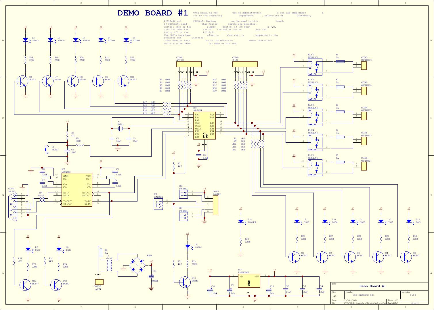
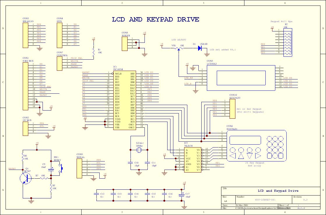
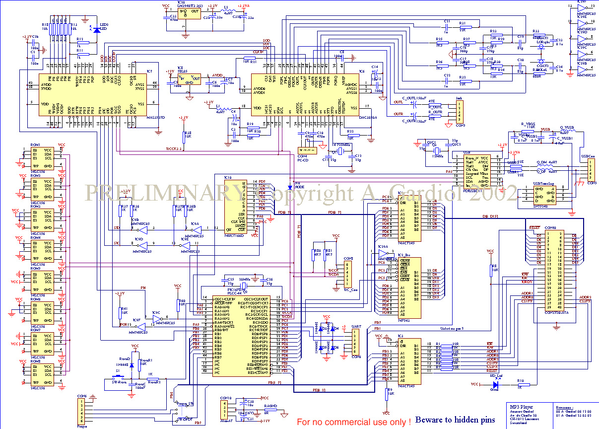
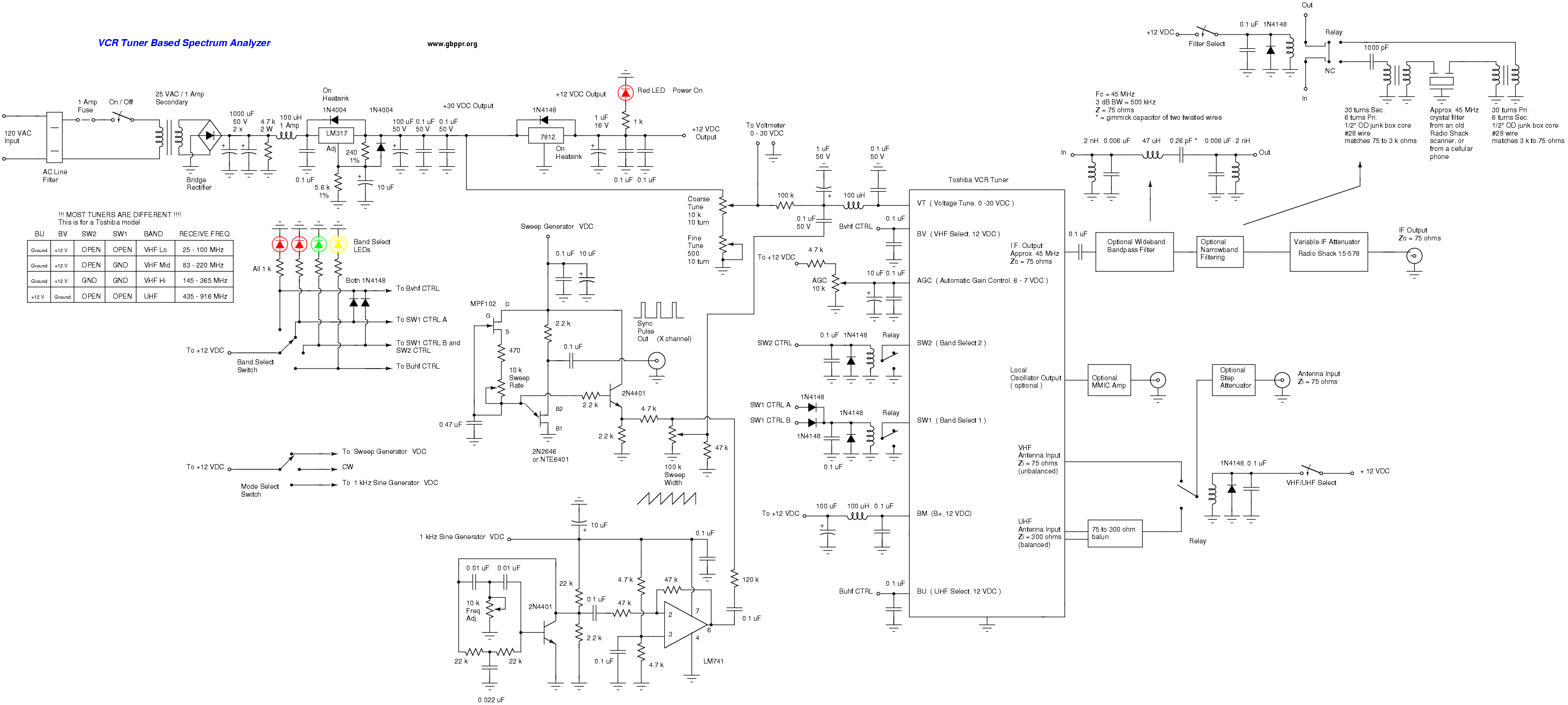
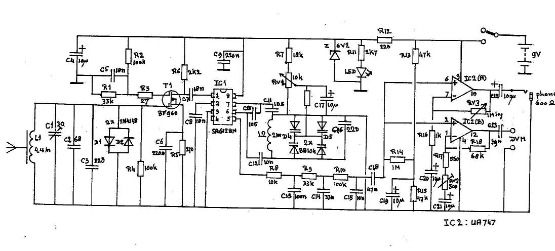