
'Arduino'에 해당되는 글 5건
- 2008.10.28 [HW] RS-232 (arduino)
- 2008.10.28 [HW] How To Get Arduino Running on Windows
- 2008.10.28 [HW] Upgrade your Arduino projects
- 2008.10.28 [HW] Introducing the latest Arduino board
- 2008.10.28 [HW] Fritzing.. (Alpha Release)
RS-232
In this tutorial you will learn how to communicate with a computer using a MAX3323 single channel RS-232 driver/receiver and a software serial connection on the Arduino. A general purpose software serial tutorial can be found here.
Materials needed:
- Computer with a terminal program installed (ie. HyperTerminal or RealTerm on the PC, Zterm on Mac)
- Serial-Breadboard cable
- MAX3323 chip (or similar)
- 4 1uf capacitors
- Solderless breadboard
- Hookup wire
- Arduino Microcontroller Module
- Light emitting Diode (LED) - optional, for debugging
Prepare the breadboard
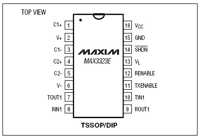
Insert the MAX3323 chip in the breadboard. Connect 5V power and ground from the breadboard to 5V power and ground from the microcontroller. Connect pin 15 on the MAX233 chip to ground and pins 16 and 14 - 11 to 5V. If you are using an LED connect it between pin 13 and ground.

+5v wires are red, GND wires are black
Connect a 1uF capacitor across pins 1 and 3, another across pins 4 and 5, another between pin 1 and ground, and the last between pin 6 and ground. If you are using polarized capacitors make sure the negative pins connect to the negative sides (pins 3 and 5 and ground).
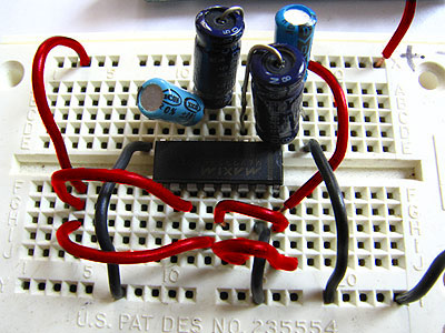
+5v wires are red, GND wires are black
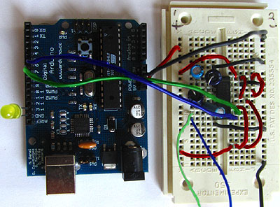
Determine which Arduino pins you want to use for your transmit (TX) and recieve (RX) lines. In this tutorial we will be using Arduino pin 6 for receiving and pin 7 for transmitting. Connect your TX pin (7) to MAX3323 pin 10 (T1IN). Connect your RX pin (6) to MAX3323 pin 9 (R1OUT).
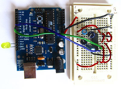
TX wire Green, RX wire Blue, +5v wires are red, GND wires are black
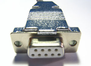
Cables
(DB9 Serial Connector Pin Diagram)
If you do not have one already, you need to make a cable to connect from the serial port (or USB-serial adapter) on your computer and the breadboard. To do this, pick up a female DB9 connector from radioshack. Pick three different colors of wire, one for TX, one for RX, and one for ground. Solder your TX wire to pin 2 of the DB9 connector, RX wire to pin 3 and Ground to pin 5.
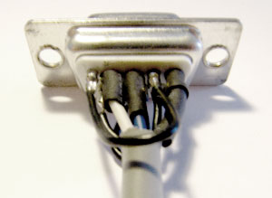
Connect pins 1 and 6 to pin 4 and pin 7 to pin 8. Heatshrink the wire connections to avoid accidental shorts.
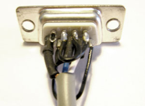
Enclose the connector in a backshell to further protect the signal and enable easy unplugging from your serial port.
Connect the TX line from your computer to pin 8 (R1IN) on the MAX233 and the RX line to pin 7 (T1OUT). Connect the ground line from your computer to ground on the breadboard.
TX wires Green, RX wires Blue, +5v wires are red, GND wires are black
Program the Arduino
Now we will write the code to enable serial data communication. This program will simply wait for a character to arrive in the serial recieving port and then spit it back out in uppercase out the transmit port. This is a good general purpose serial debugging program and you should be able to extrapolate from this example to cover all your basic serial needs. Upload the following code into the Arduino microcontroller module:
//Created August 23 2006
//Heather Dewey-Hagborg
//http://www.arduino.cc

#include <ctype.h>

#define bit9600Delay 84
#define halfBit9600Delay 42
#define bit4800Delay 188
#define halfBit4800Delay 94

byte rx = 6;
byte tx = 7;
byte SWval;

void setup() {
  pinMode(rx,INPUT);
  pinMode(tx,OUTPUT);
  digitalWrite(tx,HIGH);
  digitalWrite(13,HIGH); //turn on debugging LED
  SWprint('h');  //debugging hello
  SWprint('i');
  SWprint(10); //carriage return
}

void SWprint(int data)
{
  byte mask;
  //startbit
  digitalWrite(tx,LOW);
  delayMicroseconds(bit9600Delay);
  for (mask = 0x01; mask>0; mask <<= 1) {
    if (data & mask){ // choose bit
     digitalWrite(tx,HIGH); // send 1
    }
    else{
     digitalWrite(tx,LOW); // send 0
    }
    delayMicroseconds(bit9600Delay);
  }
  //stop bit
  digitalWrite(tx, HIGH);
  delayMicroseconds(bit9600Delay);
}

int SWread()
{
  byte val = 0;
  while (digitalRead(rx));
  //wait for start bit
  if (digitalRead(rx) == LOW) {
    delayMicroseconds(halfBit9600Delay);
    for (int offset = 0; offset < 8; offset++) {
     delayMicroseconds(bit9600Delay);
     val |= digitalRead(rx) << offset;
    }
    //wait for stop bit + extra
    delayMicroseconds(bit9600Delay);
    delayMicroseconds(bit9600Delay);
    return val;
  }
}

void loop()
{
    SWval = SWread();
    SWprint(toupper(SWval));
}
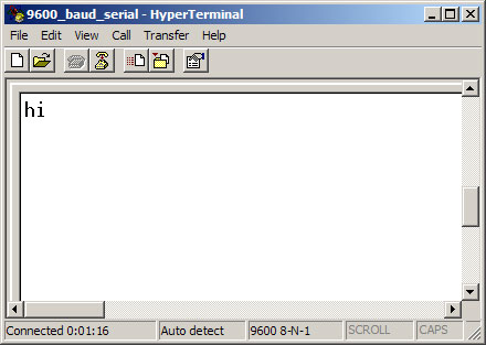
Open up your serial terminal program and set it to 9600 baud, 8 data bits, 1 stop bit, no parity, no hardware flow control. Press the reset button on the arduino board. The word "hi" should appear in the terminal window followed by an advancement to the next line. Here is a shot of what it should look like in Hyperterminal, the free pre-installed windows terminal application.
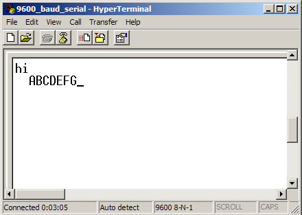
Now, try typing a lowercase character into the terminal window. You should see the letter you typed return to you in uppercase.
If this works, congratulations! Your serial connection is working as planned. You can now use your new serial/computer connection to print debugging statements from your code, and to send commands to your microcontroller.
code and tutorial by Heather Dewey-Hagborg, photos by Thomas Dexter
How To Get Arduino Running on Windows
This document explains how to connect your Arduino board to the computer and upload your first sketch.
These are the steps that we'll go through:
- Get an Arduino board and cable
- Download the Arduino environment
- Install the USB drivers
- Connect the board
- Connect an LED
- Run the Arduino environment
- Upload a program
- Look for the blinking LED
- Learn to use Arduino
1 | Get an Arduino board and cable
In this tutorial, we assume you're using an Arduino Diecimila. If you have another board, read the corresponding page in this getting started guide.
The Arduino Diecimila is a simple board that contains everything you need to start working with electronics and microcontroller programming. This diagram illustrates the major components of the board.

You also need a standard USB cable (A plug to B plug): the kind you would connect to a USB printer, for example.
2 | Download the Arduino environment
To program the Arduino board you need the Arduino environment.
Download: the latest version from the download page.
When the download finishes, unzip the downloaded file. Make sure to preserve the folder structure. Double-click the folder to open it. There should be a few files and sub-folders inside.
3 | Locate the USB drivers
If you are using a USB Arduino, you will need to install the drivers for the FTDI chip on the board. These can be found in the drivers/FTDI USB Drivers directory of the Arduino distribution. In the next step ("Connect the board"), you will point Window's Add New Hardware wizard to these drivers.
The latest version of the drivers can be found on the FTDI website.
4 | Connect the board
The power source is selected by the jumper between the USB and power plugs. To power the board from the USB port (good for controlling low power devices like LEDs), place the jumper on the two pins closest to the USB plug. To power the board from an external power supply (6-12V), place the jumper on the two pins closest to the power plug. Either way, connect the board to a USB port on your computer.
The power LED should go on.

The Add New Hardware wizard will open. Tell it not to connect to Windows update and click next.

Then select "Install from a list or specified location (Advanced)" and click next.

Make sure that "Search for the best driver in these locations is checked"; uncheck "Search removable media"; check "Include this location in the search" and browse to the location you unzipped the USB drivers to in the previous step. Click next.

The wizard will search for the driver and then tell you that a "USB Serial Converter" was found. Click finish.

The new hardware wizard will appear again. Go through the same steps. This time, a "USB Serial Port" will be found.
5 | Connect an LED (if you're using an older board)
The first sketch you will upload to the Arduino board blinks an LED. The Arduino Diecimila (and the original Arduino NG) has a built-in resistor and LED on pin 13. On Arduino NG Rev. C and pre-NG Arduino boards, however, pin 13 does not have a built-in LED. On these boards, you'll need to connect the positive (longer) leg of an LED to pin 13 and the negative (shorter) leg to ground (marked "GND"). The LED will typically be flat on the side with the negative leg. Normally, you also need to use a resistor with the LED, but these boards have a resistor built-in on pin 13.
6 | Run the Arduino environment
Open the Arduino folder and double-click the Arduino application.
7 | Upload a program
Open the LED blink example sketch: File > Sketchbook > Examples > Digital > Blink.
Here's what the code for the LED blink example looks like.

Select the serial device of the Arduino board from the Tools | Serial Port menu. On Windows, this should be COM1 or COM2 for a serial Arduino board, or COM3, COM4, or COM5 for a USB board. To find out, open the Windows Device Mananger (in the Hardware tab of System control panel). Look for a "USB Serial Port" in the Ports section; that's the Arduino board.


Make sure that "Arduino Diecimila" is selected in the Tools > Board menu.

Now, simply click the "Upload" button in the environment. Wait a few seconds - you should see the RX and TX leds on the board flashing. If the upload is successful, the message "Done uploading." will appear in the status bar. (Note: If you have an Arduino Mini, NG, or other board, you'll need to physically present the reset button on the board immediately before pressing the upload button.)

8 | Look for the blinking LED
A few seconds after the upload finishes, you should see the amber (yellow) LED on the board start to blink. If it does, congratulations! You've gotten Arduino up-and-running.
If you have problems, please see the troubleshooting suggestions.
9 | Learn to use Arduino
The text of the Arduino getting started guide is licensed under a Creative Commons Attribution-ShareAlike 3.0 License. Code samples in the guide are released into the public domain.
Link : http://www.arduino.cc/

Running out of space in your big Arduino project? Good news! Finally, after months of backorders, one can now buy the latest improvement to the 'ATmega8′ line of chips: the ATmega328's.The '328 has 32K of flash, and 2K of SRAM. Basically its got the capacity of an ATmega32 but in a slimmer package. These chips are notable for their ability to drop-in replace the ATmega168. So that means if you have an Arduino or compatible clone, it is a easy 2 minute swap.
If you have an Adafruit wave shield or GPS/datalogging shield, and you're annoyed that the FAT16 libraries eats up so much flash and RAM, upgrading will definitely fix the problem.
I've merged my previous updates to the Arduino bootloader to the most recent release and also fixed 2 annoying bugs that have prevailed this long. (1. the missing signature bytes when using the bootloader directly and 2. the broken EEPROM code). Download the '328-compatible bootloader files here.
There are 250 preprogrammed chips are in the Adafruit webshop or you can get blank chips from Mouser (but be warned that they're backordered till mid-December)
Introducing the latest Arduino board

The latest Arduino in the family is the Arduino Duemilanove (which means "2009") and includes 14 digital input/output pins of which 6 can be used as PWM outputs, 6 analog inputs, a 16 MHz crystal, USB connection, power jack, an ICSP header, and a reset button. The main difference between this and the last version, the "Diecimila" is that this version automatically selects the power source for the boards, dispensing of the old USB/External power jumpers and it also adds a way of disabling the auto-reset of the board, but includes a solder jumper just in case you need to re-enable it.
link : http://www.fritzing.org

아래와 같이 그래픽적으로 설계가 가능하다..
Starting a New Project
Let's start by opening Fritzing and creating a new empty sketch.
From the Fritzing menu bar, select File > New > Fritzing Sketch.
The New Fritzing Diagram window opens. Specify a name and location
for the new sketch, and click Finish.

The Environment
You will now notice Fritzing´s environment sections:
1. the Menu bar
2. the Tool bar
3. the Stage
4. the Palette window
5. the Properties window
6. the Overview window

Building a Circuit
We will now build a circuit by placing and connecting parts on the stage.
First, we need an Arduino board. Click on the Arduino icon in the palette
window (under Parts) and click again to place it on the stage.
Notice that a text field is highlighted. Type a name and press ENTER.

Place a breadboard, a resistor, a button and an LED on the stage.
You can organize the stage by moving and rotating these parts.
To move a part - select, click & drag.
To rotate a part - select, click & drag a parts corner.
To delete a part - select and press BACKSPACE.
For a better view of the stage, you can zoom in and out using the Zoom
tool (from the palette window) or the Zoom flip menu in the tool bar.

We can now start connecting parts together. Select the Wire tool from
the palette window and click on the LED´s "+" terminal. As you click &
drag, a wire is created. Drag the wire to Arduino´s digital pin (13) and
release the mouse button. The LED is now connected with Arduino.
Give the wire a unique name and press ENTER. Repeat the last steps
until you have all parts connected as shown in the photo below.
To bend wires, click & drag any part of a wire.

Editing a Circuit
Now that we have all parts connected, let's see how we can modify the
properties of each part. Select the resistor and have a look at the properties
window. The Core properties of a resistor are Name, Part Number and Value.
You can modify any of these properties at any time. Click on Value and type
2200 (2.2 KOhm). Select a wire and check its Appearance information in the
properties window. Here you can modify fonts, colors and routing styles.
Click on the stroke color icon and choose a new color for the wire. Choose
between oblique and rectilinear routing and adjust its smoothness as you wish.

You can leave notes on the stage by using the Notes tool from the palette window.When you're done editing your circuit, it should look more or less
like the example below.

Saving and Exporting a Circuit
Finally, save your sketch by selecting File > Save.
You're now ready to export your circuit to Eagle and create a PCB layout.
Select File > Export > as Arduino Shield PCB and follow the instructions in
the Creating a PCB Layout section.


